bltouch wiring diagram
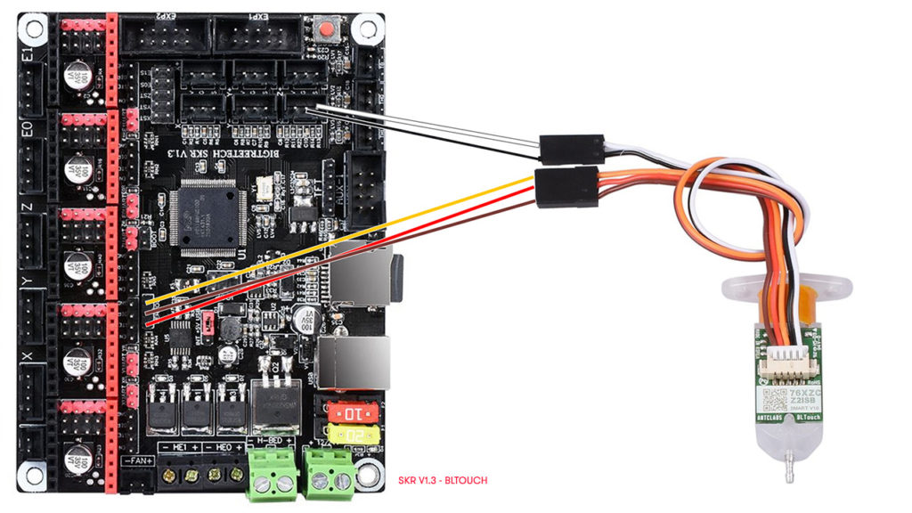
The BLTouch plugs into the SKR Mini board as shown in the image below. Servo Pin or No.
Cr 10s V2 1 Mainboard Bltouch Wiring R Cr10
In this case its safe because 5V of servo connector and VCC of RAMPS14 are seperated.

. They had signalground5v and then found ground. Anet A8 Bltouch Wiring Youtube Anet A8 Wiring Diagram Wiring Diagram will come with numerous easy to stick to Wiring Diagram Directions. 22 Wiring The 3DTouch Auto Leveling sensor has 5 wires 3 for the first servo connection and 5v and 2 for the Z min end stop negative and signal pins.
Otherwise the arrangement will not work as it ought to be. This grounds the BLtouch. Do not use jumper between VCC and 5V in this case.
Anet A8 Wiring Diagram anet a8 bltouch wiring diagram anet a8 circuit diagram anet a8 mainboard circuit diagram Every electrical arrangement is made up of various distinct parts. If you connect your bltouch and when auto homing the sensor doesnt register the z axis keeps dropping pressing into your bed turn your printer off disconnect the power and invert the black and white connectors in the z limit. Below are details on wiring your BL Touch to these boards with the 2 different methods.
Capt1701a New Member Registered. This powers the BLtouch. The 3 left over wires on the BLTouch are GND brown Red 5v and Orange control signal If you do not own a Duex expansions port and instead use the pins on the Duet Wifi you connect as shown on this diagram.
Recommended wiring for BLTouch on the SKR mini E3 v12 Recommended BLTouch wiring for the SKR mini E3 v20. If you are going to power it you need to ground it. Like a table lamp.
V20 V21 board use the same pin-out for the BLtouch if you have the V21 board follow the wiring guide for V20. - 5V for Power. The rar file i send contains a pdf file look at page 1 point 3.
GND G Brown to pin 2 on Duet WiFi. - S for Signal. I found this diagram but it is for an older version of the board.
Op 1 yr. These directions will be. Ive found one reddit post with same issue on an Ender 3 and it was just wrong wire placing.
Most Board provides its own servo pin so BLTouch can be used connected to one of those servo pins. Its a message to check Wiring because your 3D printer board is already sending a control signal to BLTouch before BLTouch power is turned on. Auto Bed Leveling Sensor for 3D Printers.
One IO for control PWM or Software PWM. RAMPS14 External additional 5V power Wiring. You can easily remove C45 by just using a long nose plier or cutter.
Image below is of the wiring harness to the x head box Solder a 2 pin male to the pins highlighted. Same for the BLtouch. In this case 12V from ATX Power is supplied to 1117 regulator on Arduino through diode D1 on RAMPS14.
It is inappropriate for it to be there. My BLTouch triggers on start up but wont trigger during homing. 3DTouch can be operated in the following condition.
Engineering plastic push-pin can be bent more easily than aluminum pins so that engineering plastic push-pin can be recovered well and the 3D printer can be protected. Check your wiring again. As each servo pin has its own number BLTouch will be controled.
If you remove C45 accuracy would be higher even though if you dont use BLTouch. However the pin used in the diagram is actually pin 44 so this is correct. It is common for BLTouch control signals to occur at machine startup or a little later.
Unit with the hotend and BLTouch attached Yellow is signal red is positive and brown is negative ie. The complete BLTouch3DTouch guide for Creality printers board follow the same pin out for the sensor as shown in the v wiring diagram. Neither method is better than the other they both work the same.
Turns out the wiring can be flipped somewhat randomly on. RAMPS14 ATX power Wiring. Yellow to D11 red to 5v and brown to GND as shown in above image.
The complete BLTouch3DTouch guide for Creality printers board follow the same pin out for the sensor as shown in the v wiring diagramSummary BLTouch is an auto leveling sensor for 3D Printers that can precisely measure the tilt of Bed surface. This is the port that the BLtouch sends the signal. PWM or Software PWM One IO for Zmin White wire.
It is intended to assist all of the average user in developing a proper program. One IO for control Orange wire. It could work with any kinds of bed materials such as glasses woods metals and so on.
- G for Ground1. And I am looking for a little guidance on how to wire the BLTouch. You need to power it for it to work.
Each part ought to be set and connected with other parts in specific way. Dont worry your 3D printer and BLTouch work perfectly even if the Red LED flashes at 80 duty. With the bltouch disconnected check that white and black wires are not shorted together on the bltouch.
The D2 pin is already wired into the wiring loom so you dont need extra wiring 5. Panucatts Viki 20 wiring diagram v12 indicates that the beeperbuzzer is connected to pin 33. Anycubic I3 Mega V2 ultrabase version MUST be the 8 bit version.
These images were taken from the BIGTREETECH GitHub site. BLTouch Smart V31 BLTouch Instruction Center Of PWM Available PWM Rage 20 G-code x. It is recommended that you use the Z endstop as the BLTouch switch instead of the alternate wiring method.
Our Unified 2 firmware is setup to use the 32 wiring pinout by default but there is also an option called CREALITY_V42X_BLTOUCH_ON_5PIN that changes the firmware to use the 5 pin header. AnetMelzi Compatible Wiring define SERVO0_PIN 27 C45 must be removed to use BLTouch. BLTouch can be operated in the following condition.
Wiring Diagram For Bltouch 02122018 1 Comments The complete BLTouch3DTouch guide for Creality printers board follow the same pin out for the sensor as shown in the v wiring diagram. And i do not know if bltouch works with marlin 119 i assume it will it is a highernewer version. I have included a picture of the circuit board for my Cr10 max.
I just got in a tmc2208 board v221 for my Ender 5 Plus and it came with literally no wiring diagrams or anything. Endstop Z-probe GND and 5V power. You can use a different Heater-pin just make the necessary adjustment in your configurations.

How To Install Bltouch On The Ender 3 Ender 3 V2 And Pro Howchoo
Installing The Bltouch Auto Bed Leveler On My Ender 3 Pro
Bltouch Sensor For Abl On Skr 32 Bit Board

Beware Of Braindead Bltouch Wiring Duet3d